This article is part of a series aimed at engaging with surveyors who deal with cracks and defects in residential properties. While many of us are familiar with diagnosing and reporting on these issues, the engineering reasoning behind our conclusions is rarely explained.
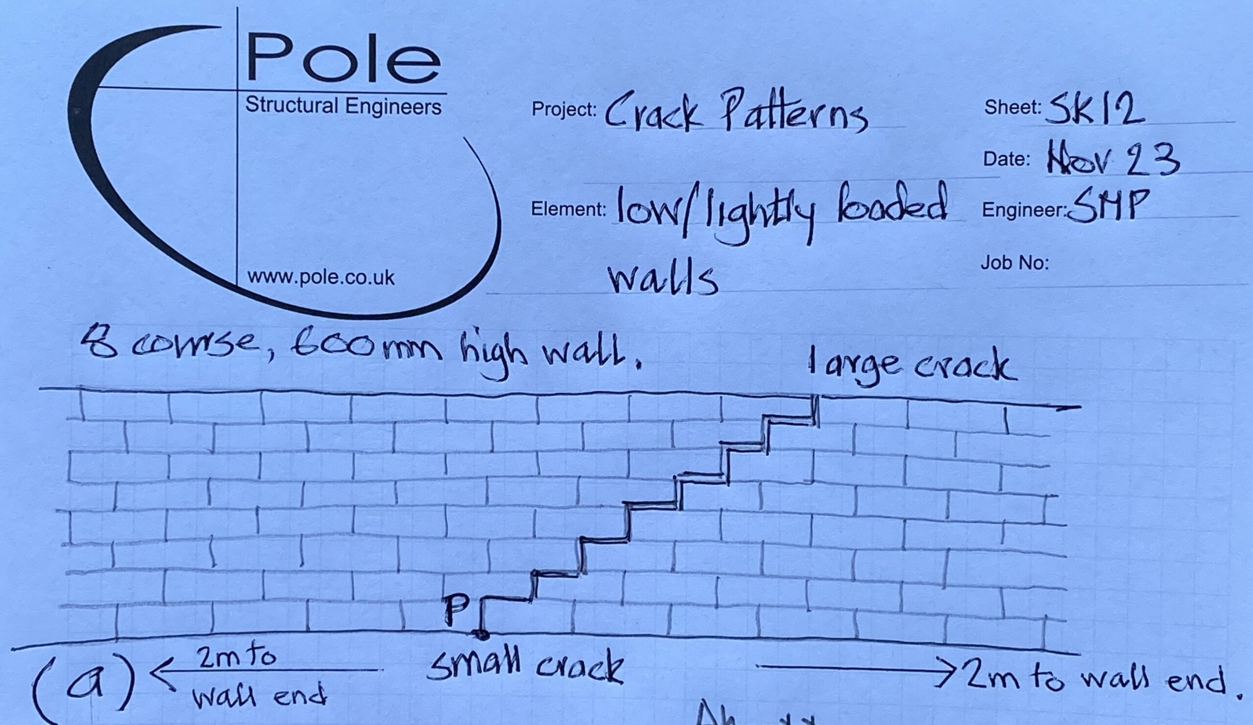
SK12 (a)
Unfortunately, there is a lack of formal reference material on crack patterns and their underlying causes. This series of articles aims to fill that gap by offering anecdotal insights
from over 40 years of experience in structural surveying and reporting on residential properties. It looks into the engineering reasoning behind our conclusions, providing both concise answers for quick reference and more detailed explanations for those with a deeper interest in the topic.
The question posed
The question refers to a low level garden boundary wall about 4m long and just 600mm or 8 brick course high. See SK12a.
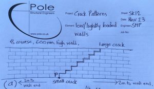
SK 12 (b)
We can confirm that the LEFT hand side of the wall has subsided but the question is “why is the crack pattern orientated as it is, sloping up and away from the area of movement in contrast to last weeks linkedin question”.
The answer in summary
In summary the left hand half of the wall pivots about the base of the crack as per the exaggerated deflected shape shown in SK12 (b).
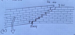
As a consequence of the downward motion of the left half of the wall, it lifts up the shaded courses of brickwork shown in SK12 (c) like a see saw. This is only possible when the wall is low and the amount of weight on the right hand end of the see saw is nominal, as the upward action breaks the mortar/ brick joints, causing the crack as it is prised upwards.
SK12 (c)
The answer in detail
This is not a trick question but is counter intuitive when first looking at the diagram, as most of us know that it is the mass of brickwork below the crack which usually moves downwards when more “weight of wall” is involved eg in higher walls or where floor and roof loads are also involved.
Normally the weight of the brickwork, or other applied loads such as roof and floor joists for example below the crack, is much larger and heavier, so the tension crack develops because the weight of the bricks below the crack exceed the tensile strength of the mortar joints between the bricks along the length of the crack.
In the case of a low or small wall, however, the shaded “corbel” of bricks lifts up with the remaining left hand half of the wall, and the wall subsides at the left hand end. And the tensile strength of the mortar joints is “broken” by that hinging action. This can be seen in diagram SK12 (c).
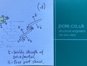
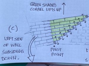
SK12 (d)
For the shaded corbel of brickwork to lift with the rest of the wall to the left, the upward force must exceed the sum of both the tensile strength of the mortar and/or the brickwork bed joints along the length of the crack, plus the vertical shearing forces between the mortar and brickwork to the vertical “perp” joints as shown in diagram SK12 (d).
Watch this space and on Linkedin for the next quiz question!
Other case studies may be of interest within our main website.


